The task of laser welding components can be difficult to accomplish and maintain in a production environment. With such factors as finding the correct laser technology, pulse length, pulse shape, terminal optics, cover gas strategy and soot control to contend with, developing a production laser welding system can be a daunting process.
Even after all of the laser details are known, you still need to reliably deliver that laser energy to the correct location on the parts. This usually involves either precision fixtures to orient the parts correctly or a skilled operator to ensure the parts are welded correctly (Photo 1). Alternatively, we’ve often integrated a vision system to automatically guide the delivery of the laser energy to help reduce setup time and scrap due to misalignment between the parts and the laser spot location (Photo 2).
Photo 1
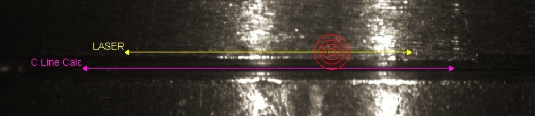
Above: The magenta line is where a vision system would find the seam. The yellow line is where a traditional laser welding system would expect to find the seam. The red target is where the traditional laser welding system would have placed the weld. This would be a rejected part.
At INVOTEC Engineering, we have successfully integrated a vision-controlled laser welding system into a wide range of custom equipment to solve complex welding problems. Using a vision system that “sees” through the terminal laser optics, we have been able to develop spot welders, seam welders and laser machining centers for the medical, electronics, and defense industries to name a few.
The vision system is able to determine where the focal point of the laser energy will land relative to the features to be welded. Once the offsets are determined (Photo 1), a servo positioning system can move either the terminal optics or the parts to be welded so that the energy is delivered to the correct weld location (Photo 2). For example, we have developed custom systems which use five servo axes to properly manipulate small parts to the correct location and specified preload forces before applying a series of tack and seam welds.
Photo 2
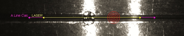
Photo 2: Again, the magenta line is where the vision system found the seam. However, in this example, the vision system automatically guided the laser to weld within the seam. The red welding target is now properly placed on the seam. This would be an approved part.
Vision guidance can be used in situations where the combination of tolerance stack-ups, beam diameter and feature size would cause inconsistent welds. Another application is for parts that need to be placed in a particular state of tension or compression prior to welding. By implementing a vision guided laser welding system, our customers have been able to get more reliable results, reduce cycle time and reduce defective welds for their manufacturing process.
You can read more about our custom laser equipment the in the laser systems section of our project portfolio.
Share this Post